Introduction

Three-phase power is the preferred type of electrical energy for most of the power transmissions in the world. This week, we will explore three-phase power, its advantages and disadvantages, and go through the math. We will also help you understand some basic parameters about three-phase power. Note that, in three-phase systems, there is not an instance in time when the output voltage is 0.

Three-phase voltages can be very large and can cause damage to you or to anyone around or behind you if you touch the wrong place. If you are not sure of what you are doing and don't have the proper equipment and supplies for working on high-voltage circuits, then LEAVE THEM ALONE and call a certified electrician. This magnitude of voltages can be lethal to the novice, and you may not get a second chance. Please take all precautions when working with any ac-power system.

Terms and Definitions

TermSymbolDefinition

Wye Configuration

Y

Generator is shown, but the load can be in a wye also.

Delta Configuration

Generator is shown, but the load can be in a delta also.

Line-to-Line Voltage

This is the voltage from one line to the other line: for example,  .

Phase Voltage

This is the voltage across the phase. Phases are represented by an inductor symbol: for example,  .

Phase Current

This is the current through the phase.

Balanced System


This means that the neutral wire has no current and that each phase has the same magnitude voltage and current. We can make a per-phase equivalent and a one-line diagram from a balanced system.

Delta or Wye Total Real Power

P

P = 3 cos

P = 3 cos

P =  cos ; Y load only

Θ is the angle between  , the voltage, and the current in any phase of the load.

Delta or Wye Total Reactive Power

Q

Q = 3  sin

Q = 3 sin

Q =  sin

Θ is the angle between the voltage and the current in any phase of the load.

Delta or Wye Total Apparent Power

S

S = 3

S = 3

S =

Common Single-Phase Systems in Your House

Common U.S. wire colors are Line 1 = black, Line 2 = red, and Line 3 = blue.

 120 Volt Single Phase (Single-Phase Two Wire)


 120/240 Volt Single Phase (Single-Phase Three Wire)

Generation of Three-Phase Voltages and Currents

Advantages of 3ø Power

  • The cost of utility power lines and distribution equipment per watt is about 25% less, and there is less line loss per watt.
  • Three-phase motors are more efficient, are easily reversible, and any motor with a rating above 7 1/2 HP must be 3ø-phase powered.
  • Multiple voltages are directly available from 3ø systems, such as 120v/208v and 277v/480v.

Disadvantages of 3ø Power

  • There is a high initial-installation cost.
  • Three-phase transformers can become unbalanced, causing voltages to become higher or lower than the rated value.
  • The unbalanced voltages could result in severe problems for single-phase motors and equipment.
  • Motor efficiency drops rapidly with a small three-phase unbalance, increasing energy cost.
  • Three-phase electrical grounding is more difficult than single phase, especially in delta-connected loads.

Common Three-Phase Voltages in the U.S.

  • 120/208 for general use and for special 208 volt motors
  • 277/480 used commonly in factories, mainly for motors and other devices
  • 2,400/4,160 special voltage for high-horse-power motors

Distribution Voltages

  • 7200/12,470 and 14,400/25,000

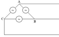
Transmission-Line Voltages: Delta

  • 46,000/69,000 and 115,000/345,000

Voltages and Currents in Wye Three-Phase Circuits

Generators at most power plants generate three separate ac-voltage sources that are equal in voltage value but are 120 degrees out of phase with respect to each other. These voltage sources are referred to as Phase A, Phase B, and Phase C, as shown in Figure 1.

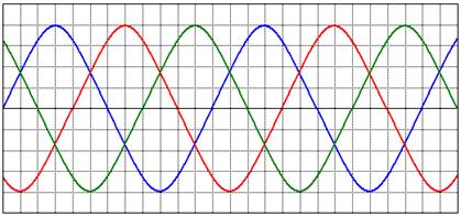
Figure 1: Phases A, B, and C of a Three-Phase System

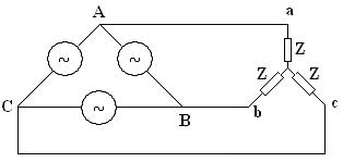
These voltage sources are connected either in Y or in  .

A Y-Connected, Three-Phase System

Figure 2 shows a Y-connected, three-phase source.

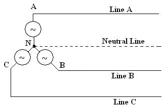
Figure 2: A Y-Connected, Three-Phase Source

pp

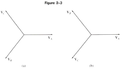
Figures 2-3a and 2-3b: Positive abc Sequence and Negative abc Sequence

There are two standards for three-phase systems, as follows.

  1. Positive abc sequence
    • Phase A is used as reference
    • Phase B lags phase A by 120o
    • Phase C leads phase A by 120o
  2. Negative acb sequence
    • Phase A is used as reference
    • Phase B leads phase A by 120o
    • Phase C lags phase A by 120o

We will use only the Positive abc Standard in our discussions. For example, if

 , then

 ;

 ; and

 ,  , and  are called phase voltages.

Example 1

Using positive abc sequence, determine  and  .

The voltage between two lines is called the line-to-line voltage, such as  ,  , and  . (Note that it is  and not  . In the abc Standard, the sequence is A, B, C, A, B, and so on. After C comes A, therefore  .)

To determine line-to-line voltages (VLL), we multiply the magnitude of phase voltages (V ) by  and add 30o to the corresponding phase angles.

Notice that EAN - EBN is shown vectorally in the diagram above.

Example 2

If  , determine all the line-to-line voltages.

From Example 1

Once we determine  , we can determine  and  using the rules of the abc sequence.

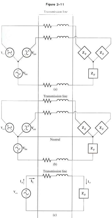
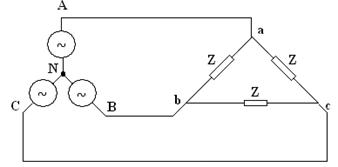
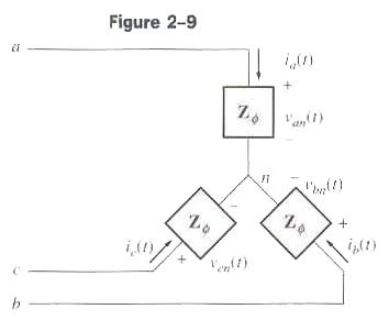
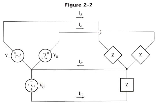
We now connect our three-phase source to a three-phase balanced load, with each load having impedance Z, as shown in Figure 3.

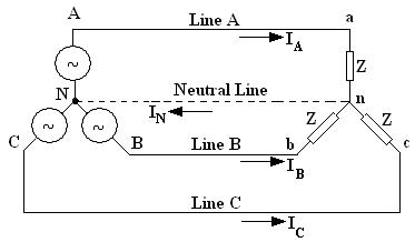
Figure 3: A Y-Y Connected, Three-Phase System

This is called a Y-Y connected source load.

Line currents are determined by solving simple individual circuits.

Example 3

For the problem in Example 2, determine the line currents if the impedance of each phase is 25 .

Example 4

For the problem in Example 3, determine IN.

 ,  +  +  =0

The result may sound surprising, but the fact is that the return current to the three-phase source is 0 if the load is balanced.

Voltages and Currents in Delta Three-Phase Systems

A  -Connected, Three-Phase System

We will now consider another configuration for the three-phase source called a  (Delta)-connected source, as shown in the figure below.

pp

In this configuration, phase voltages and line-to-line voltages are the same. Also, notice that there is no neutral line. Therefore, all three phases must be balanced.

To determine line currents, we multiply the magnitude of the phase current by  and add 30o to the corresponding phase angles.

A three-phase,  -connected source can be connected to a three-phase  or Y-connected load. In general, there can be any combination of source-load configurations.

Figure 4, shown below, is a  - connected system. In  -connected systems, the source and the load must be balanced because there is no neutral line.

Figure 4: A  - Connected Source Load

Notice in this configuration that the phase voltages are directly across the loads, or the loads are in parallel with the phase voltages.

Please redraw the figure below to look like the other delta configurations, like a triangle.

A 4-Wire Delta, 120/240/208 Volt, also known as a High-Leg Delta

Please redraw the figure below to look like the other delta configurations, like a triangle.

A 3-Wire Delta, 240 or 480 Volt, also known as a Dead-Leg Delta

Figure 5: A Y- Connected Source Load

Figure 6: A  -Y Connected Source Load pp

Power Relationships in Three-Phase Circuits

pp

The phase voltages follow.

pp 
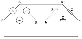
Then the phase currents are as follows.

pp

The instantaneous power for one phase is P(t) = v(t) * i(t)

With some mathematical manipulation, we have the following equations.

P = 3  cos

P = 3 cos

P =  cos , Y load only

The formulas above are for the total real power (P) in a balanced three-phase system.

Remember from last week that the reactive power is the power in a reactive device and has the symbol Q. The formulas below are for the total reactive power in a balanced system.

Q = 3  sin

Q = 3 sin

Q =  sin

The total apparent power is as follows.

S = 3

S = 3

S =

Analyzing Balanced Three-Phase Systems

 =  , and the phase is abc. Find  =  ,  =  ,  =   =  ,  =   =  ,  =   =  , and  =  if Z is 30 ohms. Find the total real, reactive, and apparent power.

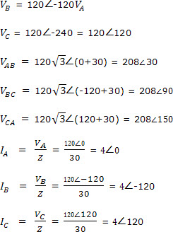
 , which is correct for a balanced system.

P = 3 cos = 3 * 120V * 4A cos0 = 1.44kw

P = 3 cos = 3 *  * 30 cos0 = 1.44kw

P =  cos , Y load only =  * 208 * 4 * cos0 1.44107kw

Note that we have a purely resistive load, so the angle between the voltage and the current is 0, and cos0 is 1.

Q will be 0 because we have no reactive devices.

S should be the same as P.

S = 3  because the P formula is the same, because θ = 0 and the cos(θ ) = 1.

S = 3

S =

Per-Phase Equivalent Circuits

If a three-phase system is balanced, it is possible to find the voltages, currents, and powers at many points with a simplified per-phase equivalent circuit.

pp

This per-phase equivalent circuit works only when a neutral is present even though it is not needed; therefore, the configuration must be a wye configuration. So, if you are given a delta configuration, it must be converted to a wye to obtain the per-phase equivalent circuit.

pp

One-Line Diagrams

As we have seen from a balanced three-phase power system, we can reduce the system down to one circuit because each phase voltage and current will be the same--just the phase angles are different. It is sometimes easier to draw the power system as a single line representing the whole three-phase power system. These one-line diagrams are simple and compact ways to represent all the connections for a three-phase power system.

The one-line diagram usually shows all the major components of the power system, such as generators, loads, and transmission lines.

Below is a power system and its one-line diagram.

Power-System Protection

Usually, three components are used to clear a fault from a power system. A fault is defined as a short between two phases or as one phase shorted to ground. The three components are a transducer that monitors the current, a circuit breaker, and a faulted line. If the current is too high, the relay engages the circuit breaker and opens the faulted line. There are overlapping zones of protection for reliability. No section of the power system is left unprotected, but the overlapping is kept to a minimum.

This is a 100-amp, three-phase circuit breaker with the contacts open. Notice the burned contacts.

This is the same circuit breaker with the contacts closed. It was taken out of service for bad contacts. Notice the size of the contacts.

Take A Look At This!

Focusing on a wye generator connected to a wye load with a common neutral, this tutorial demonstrates how to calculate the phase voltages, the line-to-line voltages, and the neutral currents.


Top